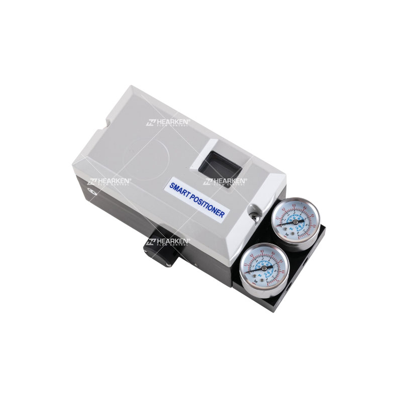
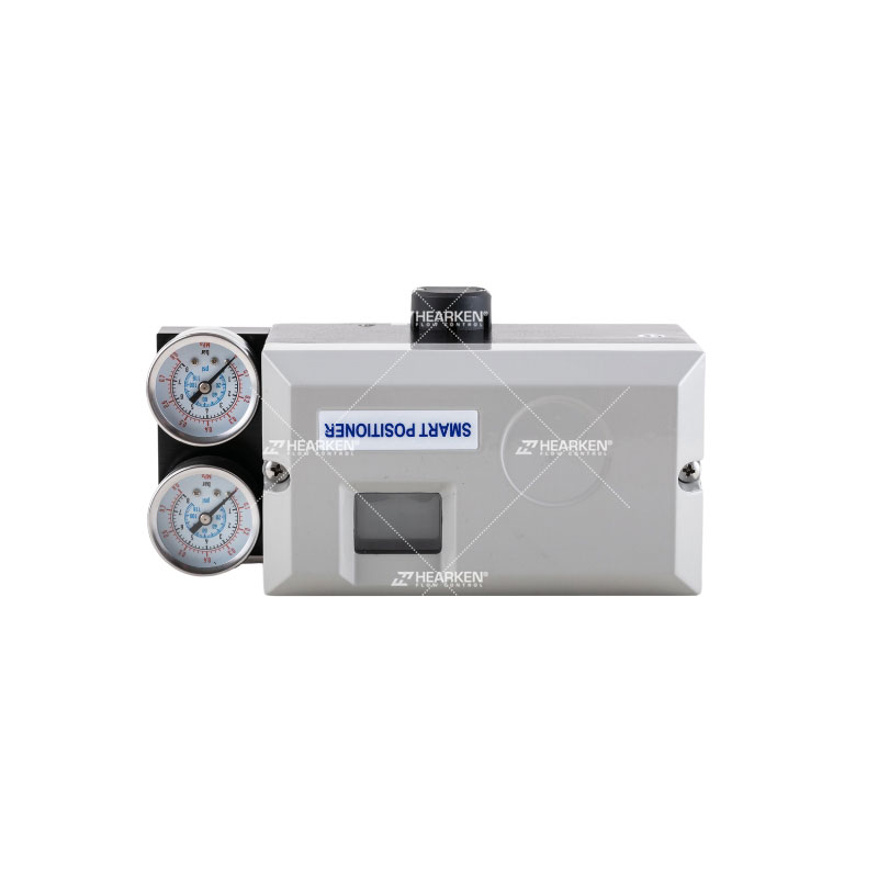
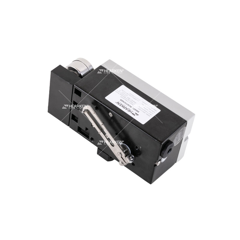
Smart Valve Positioner With Hart Communication Function

Description
Intelligent intrinsically safe positioner 4-20mA control with 4-20mA feedback.
The main technical parameters
1. Input signal range: 4~20mA; split range 4~12mA, 12~20mA.
2. Range of feedback signal: 4~20mA; split range 4~12mA, 12~20mA.
3. Equivalent resistance: 425Ω (625Ω; HART protocol type)
4. Control precision: 0.5%
5. Linearity: 1%
6. Sensitivity: self-adaptive; or artificially set during this period from 0. 1% to 5%
7. Air supply pressure range: 0.14~0.55MPa
8. Air consumption: static air consumption ≤50NL/h; dynamic non-assessment
9. Environmental conditions: temperature -25~+60℃; humidity ≤90%
10. Vibration resistance: ≤2g (5~200HZ)
11. Intrinsic safety parameters: Ui = 28VDC; Ii = 93 mA; Pi = 0.65W; Ci = 1nF; Li = 0.2mH;
12. Storage conditions: temperature -40~+85℃; humidity ≤95%
Programmable parameters
1. Input starting point range: 4~12mA
2. Input end point range: 12~20mA
3. Input signal: direction can be changed
4. Output signal: direction can be changed
5. Shut-off limit: starting point 0~10% end point 90%~110%
6. Travel adjustment: starting point 0~30% end point 70%~100%
7. Travel time: 0~200S
8. Output characteristics: linear, 1:25, 1:50 optional
9. Tolerance band: 0.1%~10% adjustable
10. PID parameters: adjustable
The security parameters are as follows:
Input circuit (terminal ± IN)
Ui = 28V, li = 93mA
Pi = 0.66W, Ci = 1 nF, Li = 0.2 mH
Output circuit (terminal ± OUT)
Ui = 28V, li = 93 mA
Pi = 0.66W, Ci = 1nF, Li = 0.2 mH
The connection between this product and the intrinsically safe end of the safety barrier should be a shielded cable with a cross-section> 0.5mm2, and the shielding layer must be grounded. The distributed capacitance and inductance of the cable must be less than the safe value. The safety barrier is installed in a safe place, and its installation and use must comply with the safety barrier instruction manual. The user is not allowed to change the electrical components in the product at will.


