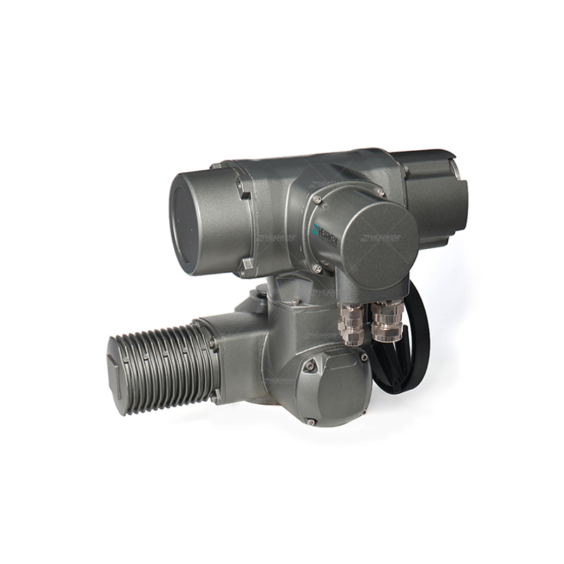
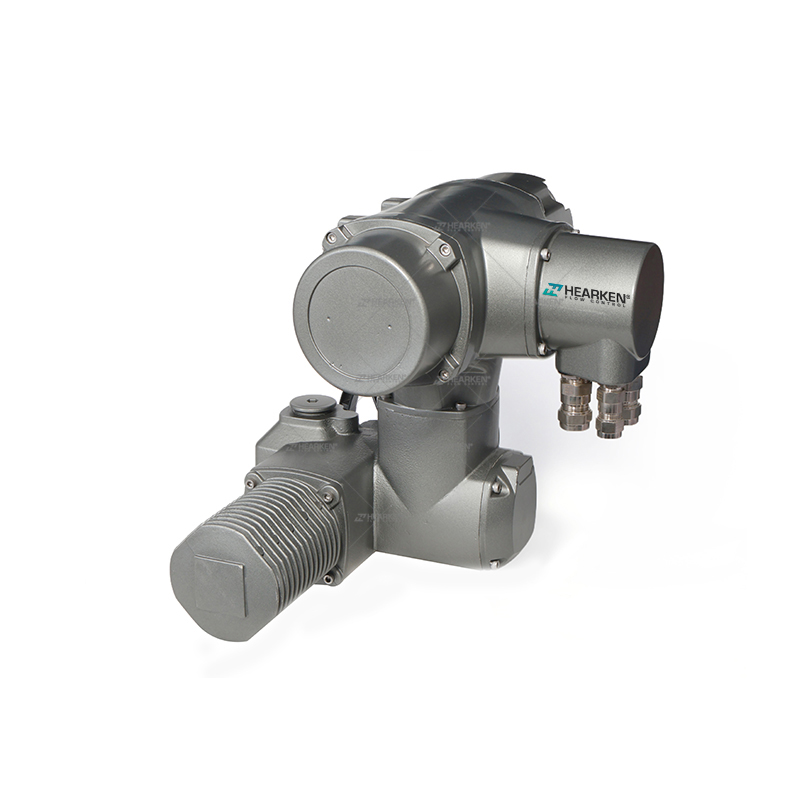
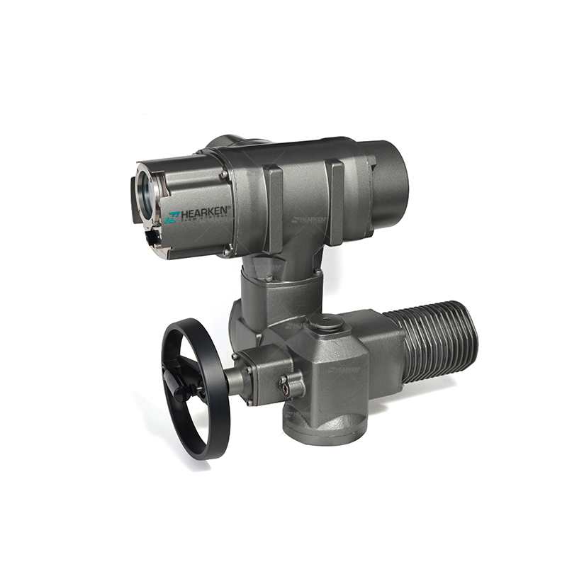
High-End Multi-Turn Intelligent Modulating Actuator With Handwheel
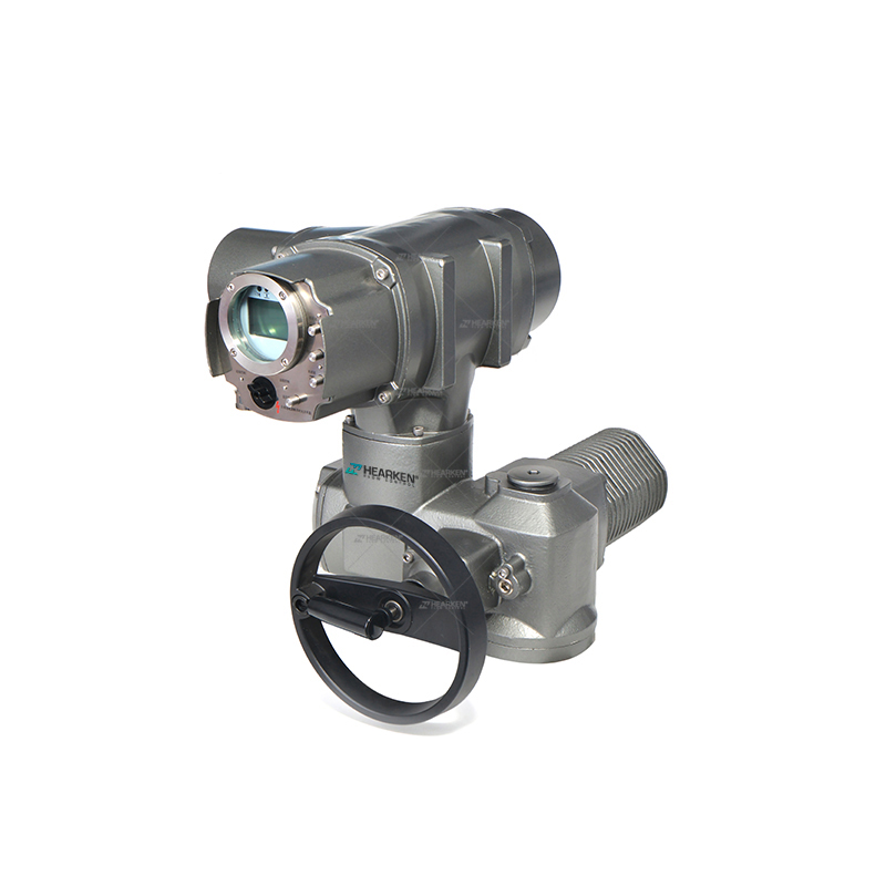
High-End Multi-Turn Intelligent Modulating Actuator With Handwheel
Item Number: HSA series
Position Feedback Signal
This control system can provide a 4~20mA position feedback siqnal.The maximumallowable external load is 7500,with an accuracy of 0.5%.(This is an optional feature.please specify if needed when ordering.)
Remote Analog (Automatic)Control
The control system can receive a 4mA~20mA analog signal for control.Note:Standard proportional control signals and proportional feedback signals are 4~20mA(can also be customized to 0-10mA,2-10mA,2~10V,1~5V.0~5V.etc. lf neededplease specify when ordering).
Operating Modes
1.1 Local Electric Operation
The actuator is equipped with a "Mode Knob" and "Operation Buttons" on itselectrical cover. For local electric operation, set the "Mode Selection Knob" tothe "Local" position, then use the "Operation Buttons" to activate the actuator.
1.1.1 Jog Operation
Press and hold the"  "button; the actuator moves towards the closing direction.Once the button is released,the actuator stops working.Press and hold the"
 "button; the actuator moves towards the openingdirection.Once the button is released, the actuator stops working.
1.1.2 Sustained Operation
Press the " " button; the actuator moves towards the closing direction.Afterreleasing the putton, the actuator continues to move in the closing direction untilthe stop conditions are met (such as torque overload.reaching the closed limit.etc.)
Press the " " button;the actuator moves towards the opening direction.Afterreleasing the button,the actuator continues to move in the opening directionuntil the stop conditions are met(such as torque overload,reaching the openlimit, etc.)
1.2 Local StopWhen the mode selection knob is set to the "Stop" position or when the "STOP"button is pressed,the actuator will disable all electric operation.
1.3 Remote Control Operation1.3.1 Remote Switch Control
Conditons for entering remote switch control mode:1.The mode knob is in theRemote" position;2. The manual/automatic switch is on.
Exterior Diagram
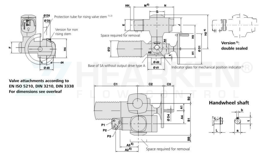
|
Dimensions |
HSA07.2 HSAR 07.2 |
HSA 07.6 HSAR 07.6 |
HSA 10.2 HSAR 10.2 |
HSA 14.2 HSAR 14.2 |
HSA 14.6 HSAR 14.6 |
HSA 16.2 HSAR 16.2 |
||
|
EN ISO 5210 (DIN3210) |
F07 |
F10(GO) |
F07 |
F10(G0) |
F10(G0) |
F14(G1/2) |
F14(G1/2) |
F16(G3) |
| A1 | 40 | 40 | 50 | 67 | 67 | 80 | ||
|
A2 5) |
199(2265)) |
199(2265)) |
199(2265)) |
209(2365)) |
209(2365)) |
209(2365)) |
||
| A3 5) | 159(188⁵) | 159(1865)) | 159(1865)) | 169(1965)) | 169(1965)) | 169(1965)) | ||
|
A4 |
103 |
103 |
103 |
119 |
119 |
123.5 |
||
|
A5 |
- |
- |
- |
8 |
8 |
15 |
||
| A6 | - | - | - | 16 | 16 | 20 | ||
| B1 | 238 | 238 | 248 | 286 | 286 | 303 | ||
| B2 | 62 | 62 | 65 | 90 | 90 | 117 | ||
| C1 | 265 | 265 | 283 | 389 | 389 | 430 | ||
| C2 | 186 | 186 | 191 | 242 | 245 | 271 | ||
| C3 | 63 | 63 | 63 | 94 | 94 | 94 | ||
| Ø D | 101 | 101 | 121 | 153 | 153 | 190 | ||
| Ø D1 | 160 | 160 | 200 | 315 | 400 | 500 | ||
| Ø D2 | G 1%4" | G 1/4" | G 2" | G 2/" | G 2%z" | G3" | ||
| Ø D3 | 42x3.3 | 42x3.3 | 60x3.7 | 76x3.7 | 76x3.7 | 89x4.1 | ||
| Ø D4 | 20 | 20 | 20 | 25 | 25 | 25 | ||
| E | 115 | 115 | 115 | 115 | 115 | 115 | ||
| F | 115 | 115 | 115 | 115 | 115 | 115 | ||
| G | 150 | 150 | 150 | 150 | 150 | 150 | ||
| H1 | 78 | 78 | 80 | 90 | 90 | 110 | ||
|
Dimensions |
HSA07.2 HSAR 07.2 |
HSA 07.6 HSAR 07.6 |
HSA 10.2 HSAR 10.2 |
HSA 14.2 HSAR 14.2 |
HSA 14.6 HSAR 14.6 |
HSA 16.2 HSAR 16.2 |
||
| H2 | 337 | 337 | 337 | 408 | 408 | 412 | ||
| H3 | 232 | 232 | 232 | 248 | 248 | 252 | ||
| H4 4) | 160 | 160 | 170 | 196 | 196 | 235 | ||
| J | 150 | 150 | 150 | 150 | 150 | 150 | ||
| L | 20 | 20 | 24 | 38.8 | 45.8 | 45.8 | ||
| M 5) | 235(262 5)) | 235(262 5)) | 235(262 5)) | 235(262 5)) | 235(262 5)) | 235(262 5)) | ||
| N | 171 | 171 | 171 | 171 | 171 | 171 | ||
| P1 3) | M20x1.5 | M20x1.5 | M20x1.5 | M20x1.5 | M20x1.5 | M20x1.5 | ||
| P2 3) | M32x1.5 | M32x1.5 | M32x1.5 | M32x1.5 | M32x1.5 | M32x1.5 | ||
| P 3) | M25x1.5 | M25x1.5 | M25x1.5 | M25x1.5 | M25x1.5 | M25x1.5 | ||
| BB min | 180 | 180 | 180 | 180 | 180 | 180 | ||
| HH min. | 30 | 30 | 30 | 30 | 30 | 30 | ||
| Ø a | 20 d7 | 20 d7 | 20 d7 | 30 d7 | 30 d7 | 30 d7 | ||
| b | 6 | 6 | 6 | 8 | 8 | 8 | ||
| Ø d1 | 90 | 125 | 90 | 125 | 125 | 175 | 175 | 210 |
| Ø d2 | 55 | 70(60) | 55 | 70(60) | 70(60) | 100 | 100 | 130 |
| Ø d3 | 70 | 102 | 70 | 102 | 102 | 140 | 140 | 165 |
| d4 | 4x M8 | 4xM10 | 4x M8 | 4xM10 | 4xM10 | 4xM16 | 4xM16 | 4x M20 |
| h | 3 | 3 | 3 | 4 | 4 | 5 | ||
| t | 22.5 | 22.5 | 22.5 | 33 | 33 | 33 | ||
