Understanding Pneumatic Control Schematics for Industrial Applications

Pneumatic control systems play a critical role in automating industrial processes. Understanding the design and function of various pneumatic control schematics can greatly improve the efficiency and reliability of equipment.
This article will walk through four common pneumatic control schematic diagrams and the essential components of pneumatic control systems to help engineers and industry professionals make informed decisions.
What Are the Components of a Pneumatic Control System?
A pneumatic control system typically includes the following key components:
1. Pressure Reducing Valve
This valve regulates the air pressure entering the system, ensuring that it remains at a safe and functional level for all components.
2. Solenoid Valve
Responsible for controlling the flow of air, the solenoid valve acts as an on/off switch in the pneumatic circuit, directing air to the appropriate parts of the system.
3. Air Control Valve
This component modulates the flow rate and direction of the air, contributing to precise control over pneumatic actuator movements.
4. Limit Switch
Used to detect the position of a pneumatic actuator, the limit switch sends feedback to ensure that movements are within defined limits.
5. Junction Box
The junction box is a central hub for connecting and organizing wiring, ensuring safe and efficient communication between components.
6. Pneumatic Actuator
Pneumatic actuator converts compressed air energy into mechanical motion, driving the movement of valves or other mechanisms in the system.
7. Valve
The valve controls the flow of the working medium (often air or gas) in the system, which directly impacts the control of industrial processes.
These components work together to enable precise and reliable operation of pneumatic control systems in various applications.
How Do Actuators Receive Signals From the Control System?
Types of Pneumatic Control Schematics:
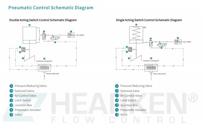
1. Double Acting Switch Control Schematic Diagram
The Double Acting Switch Control system uses both air input and output for precise valve control. Key components include a pressure reducing valve, solenoid valve, and air control valve.
Application:This setup allows for quick, reliable switching of pneumatic actuators, making it ideal for high-speed industrial applications where precise control is essential.
2. Single Acting Switch Control Schematic Diagram
The Single Acting Switch Control system simplifies operations with a single air line. Here, the actuator returns to its original position via a spring, eliminating the need for a second air line.
Application: This design reduces energy consumption and is optimal for applications requiring a fail-safe return position. Components like the air control valve and limit switch ensure smooth operation and accurate positioning.

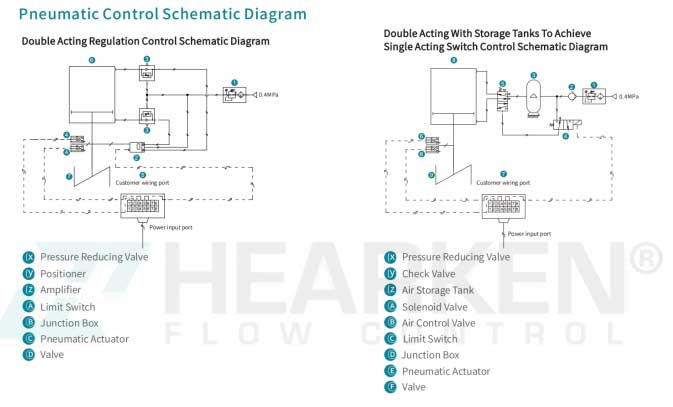
3. Double Acting Regulation Control Schematic Diagram
For applications needing continuous control, the Double Acting Regulation Control schematic integrates a positioner and amplifier. This setup enables precise regulation of valve positions based on input signals, allowing operators to control flow rates accurately.
Application: This configuration is especially useful for industries needing consistent flow control, such as in chemical processing or fluid handling.
4. Double Acting with Storage Tanks for Single Acting Switch Control
The Double Acting with Storage Tanks schematic is designed to achieve Single Acting Switch Control with an added storage tank. By incorporating an air storage tank and check valve, this setup provides greater stability and energy efficiency.
Application: It’s suitable for processes that require stable, long-duration actuation, particularly when air supply might be intermittent.

Choosing the Right Pneumatic Control System
Selecting the appropriate pneumatic control schematic depends on several factors:
Control Precision: For high precision, consider systems with double-acting configurations.
Energy Efficiency: Single acting systems or those with storage tanks offer energy-saving benefits.
Application Requirements: Assess whether the application requires simple switching or precise flow regulation.
In conclusion, understanding these pneumatic control schematics and their components can greatly enhance system performance and reliability. By choosing the right configuration, industrial operations can achieve optimal functionality, efficiency, and safety.